FAQ
Pressure Relief Valves / Safety Valves
Here you will find answers to questions about safety valves and fittings that we are asked particularly frequently.
In case you have a special questions please contact us. We will be pleased to help you and give you our advice.
What is a pressure relief valves ?
A pressure relief valve serves one single purpose: to protect against unacceptable overpressure in installations or parts of installations which would result in the system bursting. A pressure relief valve is a mechanical safety device that responds when all other control and monitoring devices fail and an impermissibly high pressure occurs in a vessel, storage tank, pipeline or something similar. For example, this can occur due to cooling failure, incorrect dosing or a blocked discharge line. If the pressure in a vessel protected by a pressure relief valve rises above a permissible value, the valve opens and allows a part of the pressurised Media to escape from the vessel. As a result, the pressure drops again. When the pressure has dropped far enough, the safety valve closes. As a result, a safety valve does not allow the entire contents of a vessel to escape but only as much as is necessary to reduce the pressure back to a permissible value.
Structure / Function
A spring-loaded pressure relief valve is a mechanical component consisting of the following main components: seat, disc, lifting ring, spring, spindle and a pressure screw for adjusting the spring preload. These components are installed in a body with connections for the supply and discharge lines and a spring housing.
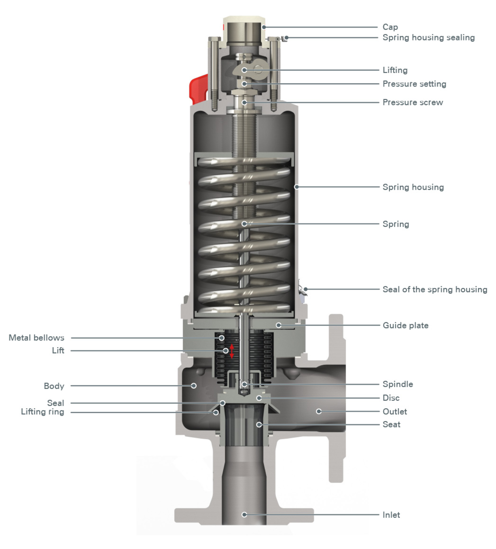
Via the supply line, the fluid enters the pressure relief valve vertically from below. During normal operation, the valve plate sits on the valve seat and closes the opening. The force required for this is applied by the spring. It is clamped between an upper fixed and a lower movable valve disc. The pressure screw, which determines the position of the upper valve disc, can be used to adjust the contraction of the spring. This results in the pretension of the spring, and therefore the response pressure. The spindle guides the disc and transmits the force of the spring via the spring plate. The seat has a defined internal diameter, which is used to determine the maximum mass flowto which the valve can dissipate, taking the flow coefficient into account.
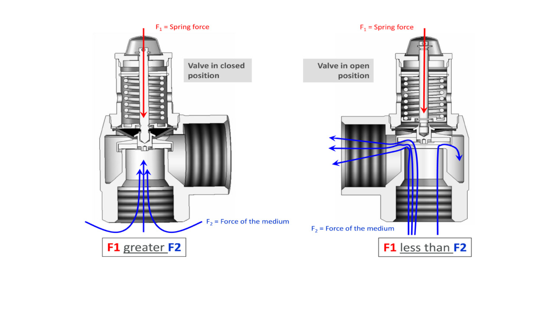
When closed, the spring force F1 outweighs the Media force F2. If the pressure in the system increases and therefore the force F2, the spring force F1 can no longer keep the valve completely closed above a certain pressure. A soft hissing sound from the pressure relief valve can be heard. This is the response point of the pressure relief valve (response point = lowest pressure at which the valve is audibly leaking). If the pressure continues to rise, the pressure relief valve opens completely and the Media can flow out.
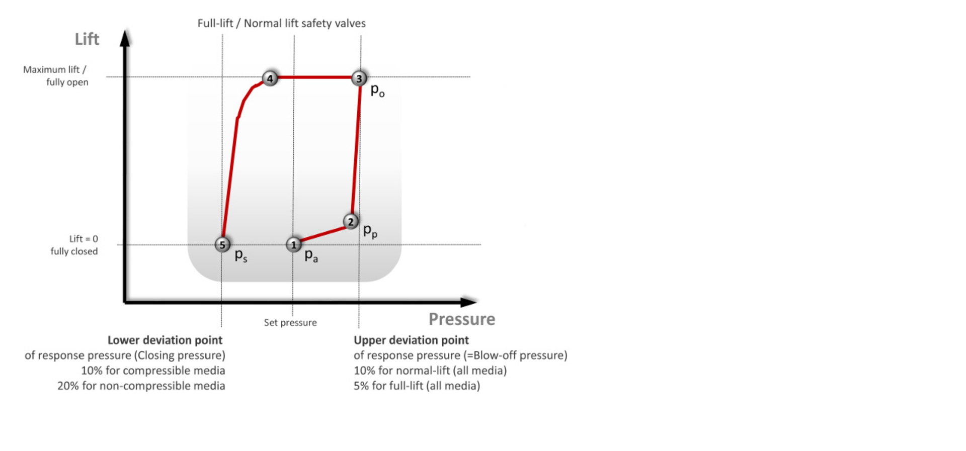
A distinction is made between pressure relief valves with different opening characteristics. The opening behaviour of a valve can best be illustrated in a stroke-pressure diagram (Figure 4) as a hysteresis curve. The stroke over the pressure is plotted in it. The regular maximum operating pressure is approximately 85% of the valve response pressure. When the response pressure (1) is reached, the pressure relief valve opens. First proportional to the increase in pressure, at the "pop point" (2) abruptly to its maximum stroke. In terms of design, this is achieved by increasing the area exposed to pressure. The pressure acts only on the cone when the valve is closed. When the pressure relief valve is open, pressure is also applied to the stroke ring. This suddenly increases the force and the pressure relief valve opens. The pressure at which the pressure relief valve reaches its full opening is the opening pressure (3) of the pressure relief valve. The pressure difference between response pressure and opening pressure is called the opening pressure difference.
If the pressure drops below the response pressure (4), the valve closes slowly at first, then abruptly again. The pressure difference between the closing pressure (5) and the response pressure is referred to as the closing pressure difference. It is caused by the impulse current of the flowing fluid and the increase in the pressure contact area caused by the lifting ring of the pressure relief valve. The pressure relief valve must comply with certain opening and closing pressure differentials (according to DIN EN ISO 4126-1 and AD2000-A2) depending on the type (standard valve or full globe valve) and Media (compressible or incompressible):
Opening pressure difference:
• 10% for normal and proportional pressure relief valve (all media)
• 5% for full stroke pressure relief valve (all media)
Closing pressure difference:
• 10% for compressible media (both types)
• 20% for non-compressible media (both types)
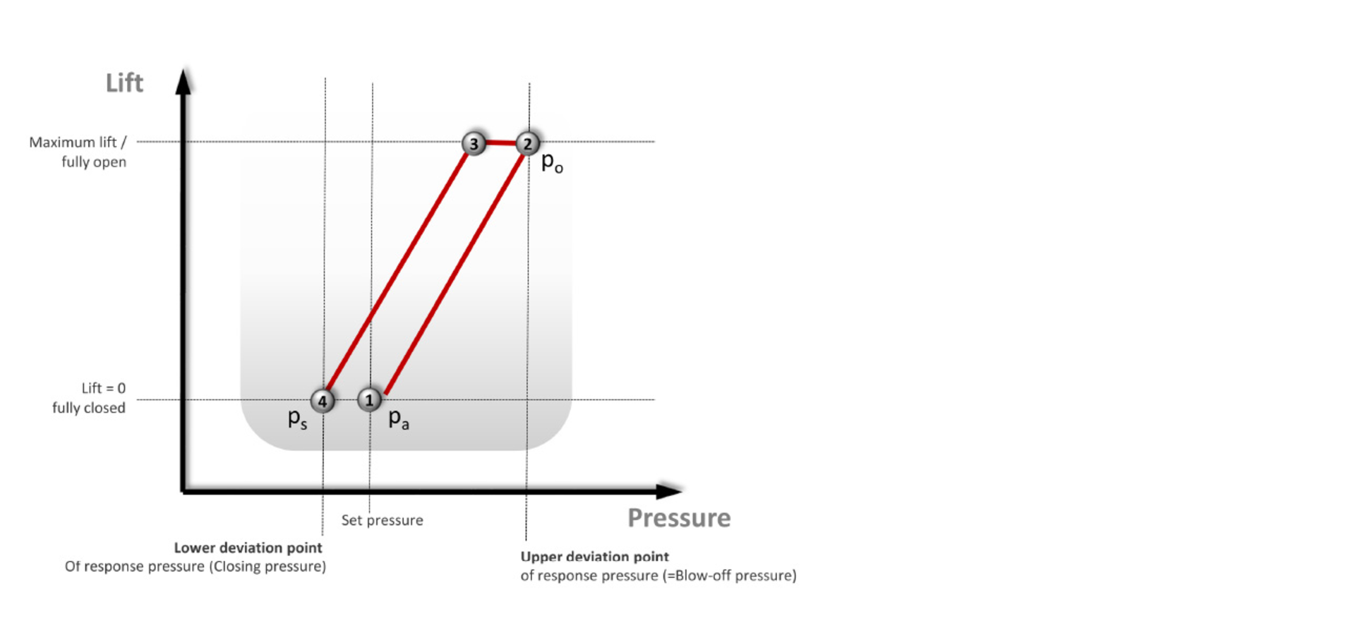
In the case of full stroke valves, there is an additional requirement that the proportion of the stroke up to sudden opening (proportional safety valves according to AD2000-A2) must not exceed 20% of the total stroke.
With the third type of valve, the proportional safety valve, the stroke of the valve increases or decreases almost continuously with increasing or decreasing pressure. A sudden opening without pressure increase over a range of more than 10% of the stroke does not occur. After tripping, these pressure relief valves achieve the stroke required for the mass flow to be discharged (DIN EN ISO 4126-1 and AD2000-A2) within a maximum pressure rise of 10%.
Variants
Various versions of individual valve components are available for individual pressure relief valve adaptation to the conditions in the plant.
Lifting
There is a possibility of a version with rotary lifting or lever lifting for manual opening and lifting of the pressure relief valve.
For a rotary lift, turning a knurled nut on the bonnet of the pressure relief valve raises the stem. This pulls the disc located on the spindle up with it. This creates a gap between the seat and disc and fluid can flow through the valve. Rotary lifting is usually used for threaded valves up to 2'' and for air and water applications.
Pulling on a lever causes the spindle and disc to lift off the seat for lever lifting. Lever lifting is usually used with flange safety valves and steam valves. For the latter, the installation of a lever lift is mandatory. A version without lifting device is also available.

Blocking Screw (Option A01)
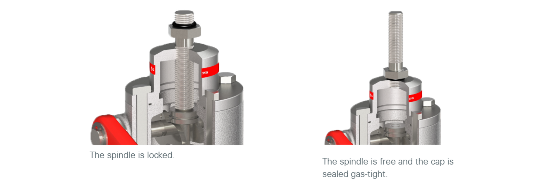
If the pressure relief valve in the system is to be closed and tight beyond its response pressure, for example for a pressure test, a blocking screw is used. This is screwed into a threaded hole provided for this purpose in the cap of the pressure relief valve from above to the spindle. This prevents the pressure relief valve from opening. After the pressure test, the pressure screw must be removed again as otherwise the pressure relief valve will not be able to open even in an emergency. Close the threaded hole in the cap with another screw.
Stroke Sensor (Option S62)
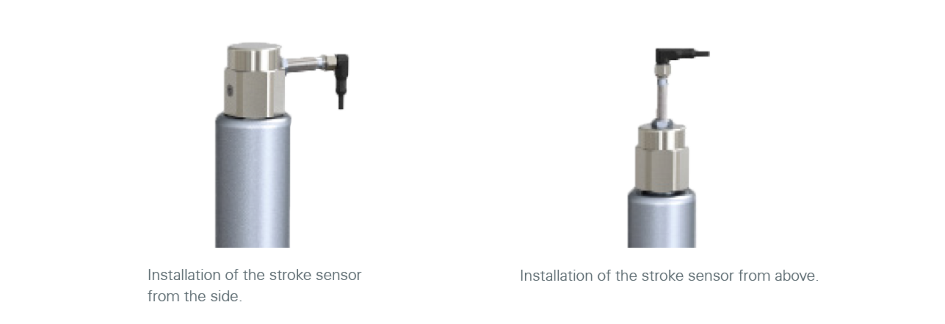
A stroke sensor is offered for monitoring the response of a pressure relief valve. This is screwed into the cap from above like the blocking screw. It strikes when the pressure relief valve reaches its full stroke. This means that the control station of the system in which the pressure relief valve is installed directly notices that the pressure relief valve has blown off. For some series, lateral installation of the sensor is also possible.
Gas-Tight / Open
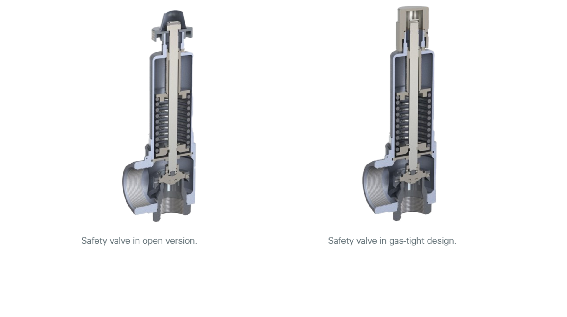
With some media it may be necessary to protect the environment from the influences of the media even when the pressure relief valve responds. Goetze offers pressure relief valves in a gas-tight version for this purpose. However, if the media does not pose any danger to the environment, an open or non-gas-tight version can be selected.
Bellows / Diaphragm
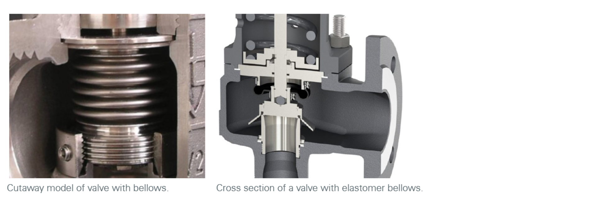
If the spring chamber must also be protected from the media in the event of a response, the use of a bellows is recommended. This connects the guide plate with the disc and thus prevents the media from entering the spring chamber through the spindle guide. In this way, it also prevents soiling or sticking of the sliding parts and ensures perfect functioning of the pressure relief valve even with sticky or viscous media. In addition, the metallic bellows compensates for counter pressure. The response pressure of the pressure relief valve remains the same regardless of whether it is an external back pressure or the intrinsic back pressure. In the event of a blowdown, the natural back pressure can build up at the outlet of the pressure relief valve depending on the dimensions and design of the installed blowdown line.
An elastomer diaphragm or an elastomer bellows can prevent the media from penetrating into the spring chamber instead of a metal bellows, depending on the pressure relief valve type, if back pressure compensation is not required and the media is neutral.
Comparison
There are different types of valves that perform different tasks in plants and require appropriate approvals and tests.
Safety valves are safety equipment in accordance with Directive 2014/68/EU, Pressure Equipment Directive. As the last link in a series of safety measures, they prevent the plant component from bursting due to an impermissibly high pressure. They are set to the desired response pressure, marked accordingly and sealed. A later change of the setting pressure is only possible in experienced workshops. The set pressure of all safety valves is checked before delivery, if required also in the presence of an inspection company. A safety valve must pass an EU type examination and, if necessary, a TÜV component test before it can be sold in series.
Pressure relief valves fulfil the same function as safety valves. However, they have no safety function and are therefore not classified as safety equipment but only as pressure equipment according to the Pressure Equipment Directive. No special examination is necessary. As a rule, they have a proportional opening characteristic. Pressure relief valves do not achieve the performance of safety valves and can be delivered adjusted, marked and sealed, but do not have to be.
The set pressure within the spring range can be adjusted by the plant operator as required in the case of overflow/control valves. They perform a "pressure control task" in the system. As this is not a safety-relevant function, overflow/regulating valves are only classified as pressure-maintaining equipment according to the Pressure Equipment Directive. No special examination is necessary. These valves have a proportional opening characteristic in order to avoid pressure surges in the system. Overflow valves must always be gas-tight.
Pressure reducing valves require a component approval for building services engineering if they are used for drinking water installations. Their task is to reduce the pressure in a part of the plant. While with pressure relief valves the presence of an excessively high pressure on the inlet side and therefore a flow through the valve is the exception, with pressure reducing valves a higher applied pressure on the inlet side is the rule. They are continuously flowed through and ensure a uniform fluid flow with constant, reduced pressure on the outlet side even with fluctuating pressure on the inlet side (e.g. after a pump).
Approvals
In order to be allowed to sell a pressure relief valve, it must pass an EU type examination and, if applicable, a TÜV component examination. Basically, an entrance examination consists of four parts:
- The test on the sufficient dimensioning of the components as well as the suitability of the materials used.
- Ensuring that the specific design requirements required by the application have been met.
- The certification of the performances (discharge figures) with the media air and water.
- Compliance with the functional characteristics (opening and closing pressure differences) with the media air and water to demonstrate suitability for:
- Air:
- Air, gases and technical vapours
- Steam
- Heating water (up to 120 °C)
- Solar heating systems
- Water:
- Liquids
- Hot water (up to 95 °C)
- Air:
These tests are described in detail in the VdTÜV data sheet "Safety Valve 100" and other applicable documents.
EU Type Examination
An EU type examination is a type approval by an independent "notified body" according to the Pressure Equipment Directive 2014/68/EU. It checks whether the minimum requirements are met for a safety valve as required in Annex 1 of the DGR and in the harmonised standard ISO 4126-1.
During a type examination, the valves can be approved for the following media:
- L for liquids
- S/G for steam/gas
The manufacturer is also obliged to supply the valve with assembly and operating instructions including a declaration of conformity in accordance with DGR 2014/68/EU. These inspection certificates are valid for a period of 10 years.
TÜV Component Test
In order to pass a TÜV component test, the requirements of the following standards must be met as well:
- VdTÜV data sheet SV 100
- AD2000 data sheet A2
This allows an additional application-specific marking of the valves:
- D/G/H for hot water with permissible flow temperatures up to 120 °C (heating systems according to DIN EN 12828)
- H for hot water of 2.5 bar and 3 bar with a permissible flow temperature of up to 120 °C and a permissible heat output of up to 2700 kW (water heating systems to DIN EN 12828)
- SOL for closed intrinsically safe solar heating systems with water or water mixtures as heat transfer media according to DIN EN 12976-1
- W for water heating systems according to DIN EN 12897 up to 10 bar
- F/K/S for stationary pressure vessels and vehicle containers for liquid, granular and powdery goods according to TRB 801 No. 22 and 23
Further Approvals
Goetze safety valves also meet the criteria for various approvals. An overview of which approvals or certificates are valid for which series can be found here.
Definition, Standards and Regulations
National:
- TRD 421: Safety devices against excess pressure
For safety valves for group I, III and IV steam boilers - TRD 721: Safety devices against excess pressure
For safety valves for group II steam boilers - DIN 4751: Water heating
For closed, thermostatically protected heat generation systems with flow temperatures up to 120°C as safety equipment - DIN 4753: Domestic hot water heaters, domestic hot water heating systems and DHW storage tanks
- DIN 4747: District heating systems
As safety-related equipment for substations, house stations and house systems for connection to heating water district heating networks - AD 2000 A2: Safety devices against excess pressure
General for safety valves
European / International:
- DIN EN ISO 4126 Reihe: Safety devices against impermissible overpressure
in particular Part 1: Safety valves and Part 7: General data - RL 2014/68/EU: European Pressure Equipment
Directive for pressure equipment with a maximum allowable pressure (PS) of more than 0.5 bar - DIN EN 12828: Heating systems in buildings
For the planning of hot water heating systems - DIN EN 12952: Water-tube boilers and system components
Particularly part 10: Requirements for safety devices against excessive pressure - DIN EN 12953: Shell boilers
Particularly Part 8: Requirements for safety devices against excessive pressure
Further application-specific standards:
- DIN EN 764-7: Safety devices for unfired pressure equipment
- DIN EN 13648: Safety valves for cryogenic operation
- DIN SPEC 4683: Liquid helium cryostats - Safety devices against excess pressure
What's the difference between a safety valve and a pressure relief valve?
Safety valve
- Certified valves with TÜV / PED and/or CE Type Test Approval
- Normal lift- Full lift opening / closing characteristic
- Higher blow-off capacities than pressure relief valves
Pressure relief valve
- Valve without certification/approval (without safety function according to PED)
- Proportional opening- / closing characteristic
- Lower blow-off capacities than safety valves
When do you use a pressure relief valve or a safety valve?
Whether a plant operator is allowed to use a pressure relief valve, or if he must usa a certified safety valve depends primarily on the type of application or plant. Both valve types are intended to be the last safety device in a system. In the case of systems or plants requiring official approval or which fall under the European Pressure Equipment Directive (PED), the valve must hold corresponding approvals and certifications.
Enquiries made easy – simple, direct, Goetze!
We will guide you through all the relevant points in just a few clicks, so that you can quickly and easily make your request. Our clear structure ensures that you receive the appropriate offer without detours.
Our checklist for selecting safety/overflow and pressure relief valves
How can I calculate pressure relief valves?
With the Go2Valves design software, calculate the right pressure relief valves for your application.
Manual sizing of pressure relief valves is history. Save time and use the new Go2Valves design software.